HPT Series Threaded Probes
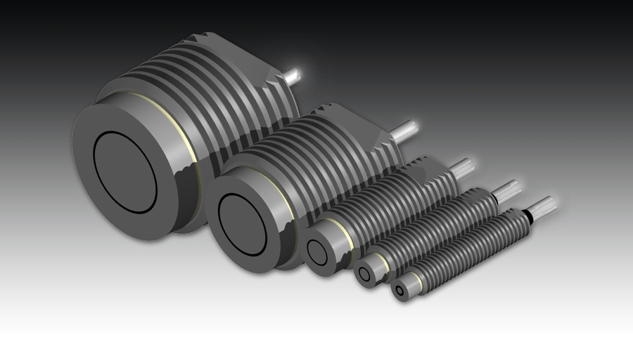


HPT Threaded Probes
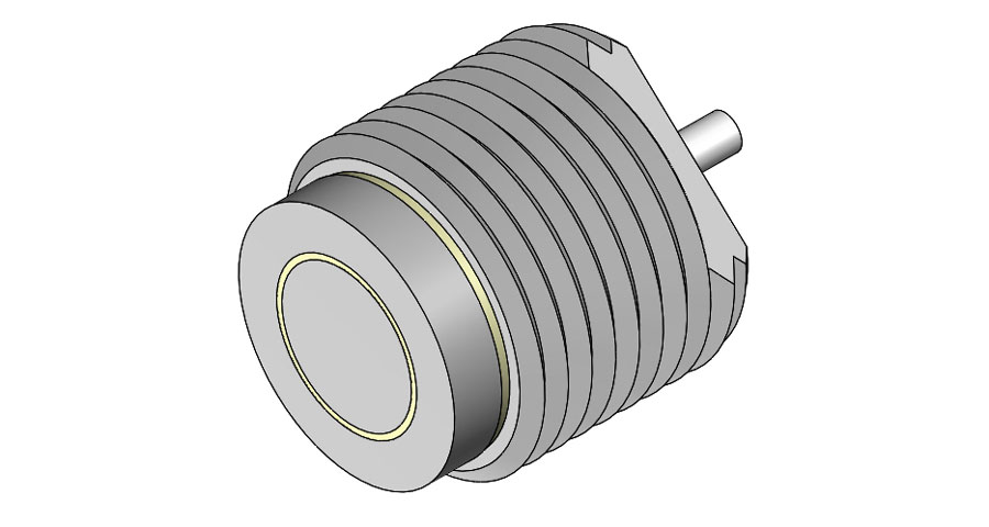
Capacitec’s HPT threaded capacitive probes can be mounted into a drill-and-tapped hole or bracket looking at an earth grounded target. The probe can be further secured in place with an optional mating nut and rotated for fine axial positioning. The sensor and guard elements of threaded probes are provided in a protective outer case to prevent shorting out of the electronics due to earth grounding the sensor tip.
HPT Threaded Probes are available in a wide operational temperature range for precise displacement measurements from Cryogenic to 1000°C.
Capacitec specializes in custom configurations. Please consult the Capacitec technical support team for more information.
Standard Sensors
size key: inch (mm)
| STYLES | SENSOR O.D. | CASE O.D. | LINEAR RANGE | MAX RANGE | THREAD SIZE | SPEC SHEETS |
|---|---|---|---|---|---|---|
HPT-40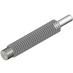 |
0.040 (1.016) |
0.180 (4.750) |
0.020 (0.508) |
0.040 (1.016) |
10-32 UNF | View Spec Sheet |
HPT-75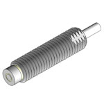 |
0.075 (1.905) |
0.250 (6.458) |
0.050 (1.270) |
0.075 (1.905) |
1/4-28 UNF | View Spec Sheet |
HPT-150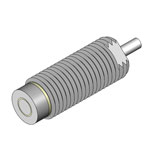 |
0.150 (3.810) |
0.375 (9.525) |
0.100 (2.540) |
0.150 (3.810) |
3/8-24 UNF | View Spec Sheet |
HPT-375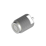 |
0.375 (9.525) |
0.750 (19.05) |
0.250 (6.458) |
0.375 (9.525) |
3/4-16 UNF | View Spec Sheet |
HPT-500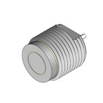 |
0.500 (12.70) |
1.000 (25.40) |
0.325 (8.255) |
0.500 (12.70) |
1-12 UNF | View Spec Sheet |
Notes
Threads:
- Thread size defined as first number = diameter (3/8); second number is threads per inch (24)
- Optional metric sizes available (Consult Capacitec technical support team)
Range:
- Range values tested with 5 ft. (1.524 m) of Capacitec L2 cable.
- Range and signal to noise ratio will be degraded by longer cable lengths.
Calibrations:
- Upon order placement customers must specify their calibration requirements. The calibration is based on the customer’s required linear range shown in voltage output per distance. All Capacitec sensor systems come with a factory calibration based on the customer’s requirements. A calibration results sheet, traceable to NIST is included in each shipment.
- A 20-point archived calibration record of voltage output vs. nominal displacement is provided standard with every probe.
- Sensor must be calibrated with final length of cable for stated results.
Electricals:
- The guard element is driven with an electronic voltage 2—20 Volts P – P maximum and must not be grounded.
- All components are electronically isolated from each other by >20 megohms of leakage resistance (at room temperature) for best operation with the instrumentation.
- -D dip coatings also prevent the driver, sensor, and guard elements from being accidentally earth grounded or shorted. (Not available on "V" and "S" Series probes.)